Troubleshooting
the Model 'A'
by
TERRY OBERER
3609 Traci Lane
Byrnes Mill, MO 63051-1047
Phone: 636-677-7201
Notes to audience:
My name is Terry Oberer and have been driving Model "A's"
since I was old enough to get a driver's license. I have been a
MARC Member since 1958 at which time we created the
Missouri Valley Region and got our charter in 1959. I was so
young that my mother or father had to drive me to the
meetings at members homes.
This will be an informal seminar so if you have a question or
comment during the talk please raise your hand so we may all
benefit from your knowledge and experience. The talk will be
illustrated with slides and the table up front will display some
of the problem parts that we will be talking about. The text of
this talk will be available at no cost in printed form at the table
up front after the formal seminar is over. Hopefully we will
have time then for some individual one-on-one discussions.
Introduction
In this session we not cover authenticity aspects or fine point
judging. We will assume that the vehicle is reasonably
authentic. We will assume that the car has been operating
normally and has developed some problem or just will not start.
Trouble shooting in the garage is easier as time and basic test
equipment is available. When an on the road breakdown occurs
many tests, while not sophisticated, can be quickly performed
which result in pinpointing common faults encountered while
driving the Model ''A.'' On the road repairs can be most often
handled quickly using a little ingenuity and common sense.
Repair suggestions and parts cautions will be made as we
proceed. What we want to avoid is a haphazard attack which
will do more damage to otherwise functional parts and end up
creating a bigger problem that the original fault. What we want
to do is look at symptoms and quickly find the defect and
correct it and any resulting faults.
Engine
Here we will assume that the engine has quit suddenly while
driving and will not restart. Remember that an engine needs
three basics in order to run - Fuel, Compression and
Ignition in proper quantity and sequence. A few simple tests
can narrow the problem area very quickly.
Fuel
Sudden stoppage can be caused by dirt or debris blocking fuel
delivery. Quick test for fuel: Crank engine with starter six or
seven revolutions fully choked. Stop cranking and release
choke. Fuel should dribble out of carburetor throat. If it does, go
on to ignition test. If no fuel is seen check for fuel in tank. Don't
trust the gauge. Remove the cap and while doing so listen for a
sucking in of air which would indicate a plugged vent causing a
tank vacuum. Remove filler safety screen and use a dip stick.
You should have at least two to three inches for reliable
delivery. If ok, remove fuel line at carburetor. A full stream
should flow when valve is turned on. If not, turn line up or use
a rubber hose over the end and blow back into the line and
tank to clear debris. The use of a tank valve screen will help to
avoid this problem. Older tank sloshing compounds may be
turned to jelly by alcohol laced fuels. This problem can be
almost impossible to cure on the road short of rigging up a
separate fuel tank. Best solution is don't let it happen in the
first place. Use only non-alcohol blended gasolines.
Carburetor: If fuel supply to carburetor is ok but no fuel
dribbled out while choking then remove lower casting center
bolt and carefully disconnect choke rod to allow the lower
casting to separate from the upper (attached) casting. Do not
allow venturi and gasket to fall. Turn on fuel and it should
cascade down over the float. If not check for plugged inlet
screen or fuel valve by removing these parts one at a time.
Blow out float valve. Check screen and also insure that the end
of the fuel line does not extend past ferrule more that 1/8 inch
or it may be up against the filter screen and flow will be
restricted.
Note: Sudden excessive fuel or overly rich mixture can also
cause engine to quit. Black exhaust smoke, smell of rich mixture
exhaust or overflowing carburetor would be indicators. Check
float valve for debris in valve preventing proper seating. Check
that float still floats and has not developed brass stress crack or
pinhole leak. Solder or shellac shut after draining float. Check
float pin for being too short and falling out of pivot. Check float
valve body for looseness or split gasket. Check main and cap
jets for looseness, splits, or bad gaskets. Check that main thru
bolt is snug - carburetor will run rich as main bolt backs out
and lower casting starts to drop from upper. Venturi maintains
air stream while bowl fuel level rises and fuel spills from throat
jets into the air stream.
Hot weather fuel problems are more common now than some
years back due to the lowered vapor pressure of current
production gasoline. The ''A'' will run fine until a stop is made in
hot weather and upon restarting run rough and rich due to the
fuel boiling in the carburetor bowl and causing erratic fuel level
problems. It will generally lessen as the car is driven (if
possible) and the vaporization of fuel cools the carburetor body.
Application of water or ice to the carburetor bowl area can be of
great benefit. The addition of a thermal break spacer between
the manifold and carburetor as on modern cars can also
alleviate this problem.
Ignition
This is the most common area of on the road failures
encountered in driving the Model A. We have a basic quick
check here and then we'll use a simplified system diagram to
isolate the trouble component and then explain various repairs
and show some areas to anticipate and prevent problems.
Quick test for spark: Disconnect one spark plug brass strip from
the distributor terminal and position it with about a 1/4 inch
gap to the distributor terminal. Turn on the key and crank the
engine. A bright fat bluish-yellow spark should regularly jump
the gap. The spark should be as thick as a pencil lead and
produce an audible snapping sound. This indicates spark is good
but timing might possibly be incorrect due to a insecure cam
lock screw. The correct procedure to check timing is as follows:
First set point gap to .010 to .022 of an inch with the point fiber
block on the high point of the cam. Check all four lobes for
uniformity of gap. (Plus or minus .002) It is best to set gap at
high side since rubbing block wear will cause gap to decrease.
Manually check distributor shaft for excessive side play (.001 to
.003 is normal). Less play means a smoother running engine as
the shaft won't chatter while rotating and result in variable
point gaps. Also check the upper plate for excessive lateral play
around the center hole as wear here will contribute also to
variable point gap when advancing or retarding the spark.
These variances from the ideal are all cumulative and can result
in excessive tolerances resulting in poor or no ignition. Once the
point gap is set replace the distributor Bakelite body and move
the spark arm to the full retard (towards the starter) position.
Remove the timing pin and insert it into the timing hole.
Remove the rotor and manually slowly crank the engine until
the pin just drops into the slight recess in the timing gear. At
this position the next instant of engine rotation should just start
the points to open and the notch in the cam should be near the
number one cylinder contact in the distributor body. (While
standing at the manifold side of the engine and looking down on
the distributor it is in the approximate four o'clock position.)
Remember that the distributor turns in a counter clockwise
direction. If timing is not correct, loosen the cam lock screw and
turn the cam clockwise to the correct position and re-tighten
the lock screw. Turn the engine two full revolutions and recheck
that the points just start to open the instant that the timing pin
drops into the timing gear recess. Readjust as necessary. Make
sure that the cam does in fact lock to the shaft. Some shafts
have poor fitting cam collars or the lock screw may need a
washer under the head. If rebuilding the distributor, you may
want to drill the upper shaft and lock screw for oil access to the
upper bushing to reduce wear. The use of the distributor heat
baffle can prolong condenser life. Manifold heaters also tend to
overheat condensers and some heaters make it impossible to
remove the condenser without removing the whole distributor--
not an enjoyable task on the side of an interstate in rush hour
in the middle of an August heat wave.
If spark and timing are correct but the engine still does not
start, then check for the third engine essential--Compression; to
be covered later.
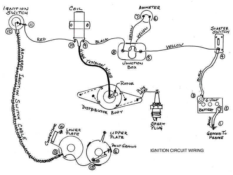
CLICK FOR LARGE DRAWING
If spark is not present when the engine is cranked with ignition
on, then a systematic trouble shooting of the ignition system
must be performed. Referring to the basic ignition system
diagram we see a series of components and their connections to
each other. A fault in one or more locations will create a ''short''
or ''open'' in the circuit resulting in a no spark situation. The
ignition system is but a simple series circuit with a voltage
source--the battery; a coil to produce a secondary or high
tension spark, a means of switching the coil on and off in time
with the engine--the distributor; a cam operating the points,
and the coil high tension wire connecting to the rotor to
distribute the spark to the appropriate spark plug. Also into this
circuit a driver controlled keyed switch is placed to ''open'' or
''close'' the circuit at the driver's will. The series of components
are as follows: Battery voltage source at the battery #3. To the
starter switch terminal #4. From the starter switch to the
terminal box stud #5. From there to one side of the ammeter #6.
Thru the ammeter to the other ammeter stud #7. From the
ammeter back to the other stud of the terminal box #8. Now we
begin the actual ignition circuit at the terminal box with our six
volt supply going from stud #8 to the coil battery terminal #9.
Thru many fine windings of copper wire in the coil to the other
terminal, the distributor side of the coil #10. However, before
we run to the distributor a driver key controlled switch is
placed in the circuit terminating at #11 and switched on and off
internally at #12. From the switch the lead runs in a
tamperproof armored cable to the base of the distributor for
connection at #13. A condenser is attached here to prevent
excessive arcing at the points and can be considered to be an
''open'' in the circuit when operating normally. From the base
plate connection #13 the short pigtail wire #15 connects the
switch to the points where they can then make and break the
connection to ground #16 by the action of the cam which is
timed to engine rotation. The high voltage is distributed
sequentially to the spark plugs by the coil wire and rotor to the
distributor body and then to the spark plugs. This is a totally
separate system but is combined with the rest of the distributor
for simplicity of construction. Quick test: Check both coil
terminals for 6 volts #9 and #10 on diagram. Use volt meter (or
just a wire touched to a ground) between each terminal and
ground with the switch off. The black lead comes from the
generator side of the terminal box #8 and should always show
six volts. The red lead goes to the ignition switch #11 and
should always show six volts when the switch is off and zero
volts when the switch is on with the points closed. If no voltage
reading is detected at either terminal check to see if the lights
work which would indicate satisfactory battery and wiring
condition thru the terminal box. If lights do work then remove
terminal box cover and see that the black wire from the
terminal box stud to coil terminal is tight and in place. You
should now have six volts at the battery side of the coil
terminal #9. Disconnect the red coil to ignition switch lead and
then check for six volts at the ignition switch side of the coil
terminal #10. If you now have six volts, then there is a short in
the ignition switch circuit. The short could be in the switch
assembly and you would be able to get going again by removing
the switch cable from the distributor base and hooking a
jumper between the coil terminal where the red ignition switch
wire was removed #10 and the distributor base condenser
screw #13. Or the short may be farther down the circuit in the
distributor.
Namely in the lower plate #13 and its associated wire #15 and
connection to the point stud. Or the condenser #14 may have
shorted out. The most common and easiest to correct is a
shorted condenser so the logical step is to remove the condenser
and then again check to see if you have six volts at the ignition
switch lead coil terminal #10. If the above test showed six volts
at both coil terminals with the ignition switch off, remove the
distributor cap and crank the engine by hand until the points
are closed. Slip a clean piece of paper between the points and
turn the ignition switch on. If the ignition switch and condenser
is good there should be a six volt reading at both coil terminals
and at the point stud #15. If you get a zero volt reading at the
ignition switch coil terminal #10, either the switch or the
condenser is shorted. Remove the condenser from the
distributor. If you now have a six volt reading at both coil
terminals, then the condenser is shorted and must be replaced.
If removing the condenser did not result in a six volt reading at
both coil terminals #9 and #10, then the ignition switch or
lower plate and wire to the points is shorted. If the switch is
shorted it must be removed from the distributor since it will
ground out any jumper if left in place. As a matter of fact a
properly working original pop out will ground the distributor
when in the off position rendering a ''jumper'' useless unless the
switch cable is physically removed from the distributor base. Be
sure to remove the paper from between the points before
trying to start the car. Quick test for proper ignition operation:
Crank engine until points are closed. Turn on ignition switch.
Remove coil wire from distributor cap and hold end of wire
within 1/8 inch of a head nut and open and close the point arm
with your finger. A fat spark should occur each time you open
the points. Be sure to turn the ignition switch off when finished
as leaving the switch on with the points closed can overheat and
burn out the coil and burn the points.
Common ignition trouble areas:
Blown fuse at starter (if equipped), Corroded or broken ignition
switch contacts, Shorted (old) wire in the pop out cable, Shorted
lower plate bus bar due to loose rivets and cable end spring
pressure, Shorted lower plate wire to points due to connection
failure or worn insulation, Shorted condenser due to heat
and/or moisture. Points physically closing but not making
electrical contact due to oxidation (Usually from long storage or
moisture or oil on the points), File to get going again. If a fuse
blows while driving, the generator system voltage rises and will
also cause oxidation or burning of the points. After correcting
the cause of the blown fuse and replacing any light bulbs that
burned out from the excessive voltage, the points may have to
be filed to get the car running again. Point fiber rubbing block
may be worn down causing the cam to short to the point fiber
block rivet head. Coil may have good spark when cool but go
open circuit or short circuit when warm. Coil high tension wire
should be of the metal core type, not resistance type as a bad
spot will allow good idle but poor high speed performance due
to weaker spark at higher RPMs. Distributor's Bakelite body
may have cracks allowing moisture to enter and cause mis-
firing or cross firing between cylinders one and two or, between
three and four.
Compression
Reduced or lack of compression will cause an engine to loose
power or stop completely. Quick test for compression: Remove
all four spark plugs. Place your thumb over a spark plug hole
and with the ignition off, crank the engine several revolutions.
The compression, if adequate, should forcefully blow your
thumb from the spark plug hole. If using a gauge it should
register from 45 to 65 psi after three or four compression
strokes. Look for uniformity of readings of no more than ten psi
difference between the highest and lowest cylinders. Low
compression on all cylinders--Check that timing gear has not
stripped by removing the distributor cap and crank the engine.
If the rotor moves the timing gear is good If the rotor does not
move confirm a bad timing gear by removing the timing pin
and reverse it in the hole and while cranking the engine ''feel''
if the gear moves. If it does not then the gear is stripped and
will have to be replaced to get going again. The use of a good
quality laminated fiber (not macerated fiber) gear is
recommended. Sometimes the metallic center hub of a gear can
break loose from the fiber portion. The gear will run but with a
distinct knock similar to a worn tooth knock. An aluminum or
brass gear can be used for severe service. Be sure to replace the
crank gear also as it also wears but not as visibly as the fiber
gears. Check that the crank gear is correctly marked with the
alignment mark to the right of the key way. Once in a while one
will be incorrectly marked. To reduce timing gear wear an oiler
can be fabricated from a standard bolt to replace the side
timing gear cover upper bolt and some tubing. The oil supply is
from the oil pump plug in the block and is metered by a 3/32
inch hole drilled in the short length of copper tube soldered into
the end of the bolt. The hole is drilled so as to spray the oil
directly on the gear. It works !
Lack of compression on one or more cylinders--Possible causes
are: A ''burned'' exhaust valve. A ''blown'' head gasket
(generally between cylinders one and two or three and four,
which would show up as low compression readings on
both adjacent cylinders). A foreign object lodged under valve
head (possibly a carburetor jet) under an intake valve. Can
cause loss of power in adjacent cylinder due to fuel being fired
in the paired intake port). Illustrated is a jet which would lodge
in the valve at speeds over 38 MPH but drop out and allow
normal valve action at lower speeds. It was not discovered until
the manifold was removed for inspection and re-surfacing. A
burned piston due to running with an antifreeze leak into the
combustion chamber can erode a significant portion of the
piston to cause compression loss. Broken rings and/or scored
bore will cause low compression. Illustrated is a piston from an
engine with less than 500 miles which was run without water
until it seized due to heat. Upon cooling and the addition of
water a distinct knock was heard. Cylinder number three was
found to be scored and this was the piston from that bore. A
minute crack had developed in the piston from the seizure and
the opening and closing of the crack during engine operation
was causing the knock. Replacing the one bad piston, honing of
the bore and replacement of all piston rings restored the engine
to use. Excessive blow by from the crankcase breather is an
indication of compression leakage past the piston and rings. If
compression readings are increased ten to twenty psi upon
squirting oil in the cylinders, it would confirm worm rings.
Adequate compression on all cylinders, No distributor
movement--Possible causes are: Loose cam locking screw, re-
time and re-tighten screw securely. If it won't stay tight check
the distributor shaft collar as some collars just slide down the
shaft. Cam lock screw may need a washer under the head. If
cam is secure to shaft, the distributor drive gear (accessible
through the valve chamber) may have a broken drive tang or
the press fit of some replacements will allow the gear to spin on
the shaft. Replace if required. A broken distributor shaft drive
tang due to seized bushings from lack of lubrication or extended
storage can also be a problem. Replace distributor shaft as
required.
Water pump and fan
Many fractured and thrown fan blades can be avoided. Always
before any tour check the fan blade hub area for an indication
of a crack. Any blade showing signs of a crack should be TIG
welded not brazed. A thrown blade can kill or injure an
observer and can do serious harm to the hood and radiator. A
common cause of the cracks is turning the engine over by
pulling on the fan blade. Don't do it ! Always check the blade for
running true after mounting on the water pump shaft and
straighten and balance as required. On 1928 - 29's check that
the blade does not hit the upper radiator hose or clamp. If you
do throw a blade on a tour, if the radiator isn't damaged, you
can continue on your way by breaking the other half blade off.
That way there is no unbalance and the waterpump is still
functional. The ram-air effect will keep the car cool unless you
are in slow traffic. Watch the temperature! On long tours a
spare blade may be helpful. Many replacement waterpumps are
assembled with the front bearing race split in the bottom of the
bore. On any pump remove the front bearing and make sure to
have the split at the top (no load) position. A lot of kits use a
brass sleeved steel rear bushing and a steel nut. The steel nut
can rust to the steel bushing during a non-use period and
results in not being able to tighten up the packing nut.
Sometimes the shaft will seize in the bushing and the bushing
will spin in the casting. The use of a solid brass bushing and
brass or die cast pack nut eliminates these problems. Some of
the packings are not suitable. Use only pure lead and graphite
packings. Don't use any with hemp or fiber in their makeup.
Some of the new pack nut seal kits work well too. Check the
impeller fit on the shaft before pressing it on, some are too tight
and will crack the impeller. Despite the instructions in the kits,
it is necessary to pin the impeller to the shaft. More than one
radiator has been destroyed by having the ''press fit'' let go!
Clutch and linkage
External linkage failure indicated by pedal falling to floor. Shift
transmission to neutral while releasing throttle to remove gear
load in transmission allowing easy shift lever movement. Coast
to safe pull off and inspect external clutch linkage for missing or
broken part. Common failure point is a replacement cast iron
not forged like original trunnion (the threaded adjusting rod).
Sometimes the lever pin can shear or the trunnion nut will pull
out of the pedal due to excessive wear from lack of lubrication.
(But we would never let our beloved A's to wear that far
without some attention.) External release shaft levers have been
known to break or wear out. Here replacement is the solution
and can easily be done on the car. For an easier-to-use clutch a
1928 multiple disk clutch arm can be fitted with only minor
filing of the pedal required for clearance of the trunnion
threads. Clutch pedal adjustments are slightly more frequent
and exacting but it is worth it, particularly in parades.
Internal Only rarely will the internal release fork break though
the shaft pin can shear. Disassembly is usually the only cure.
Sometimes the release bearing lubricant dries out and a squall
will be heard when depressing the clutch pedal. If greasing the
release sleeve fitting does not get lubricant into the bearing,
then a temporary fix is to drill a 1/8 inch hole in the bearing
outer shell and use a pump oiler to get some 600W transmission
oil directly into the bearing. Then plug the hole with a tooth
pick. It worked for me!
Non-releasing clutch can be caused by extended damp storage
causing the disk to rust to the fly-heel or pressure plate.
Generally happens when all parts are new freshly machined,
assembled and then stored. Sometimes if not too seriously
seized it can be broken loose by putting the car on a concrete
surface and vigorously rocking the car fore and aft with the
transmission in reverse while someone holds the clutch pedal
down. Lately a new clutch problem has appeared with the
presence on the market of the Ock brand Japan made spring
center disks. These disks appear to be good quality and are
exact reproduction of the American made ones except the metal
is not tempered. When in use the springs seem to work out on
the flywheel side and then jam between other springs and the
flywheel mounting bolts. This jams the clutch disk and it will
not release by depressing the pedal. The only fix here is
disassembly and replacement.
Transmission
Most transmission problems can be traced to worn gears shafts
and bearings which will normally be replaced during rebuilding.
On occasion a gear tooth may be chipped or broken due to a
missed shift. The transmission case should be drained and
cleaned of any pieces as soon as possible to prevent further
damage from the pieces being picked up and meshed into the
gears with disastrous results. Worn gears with tapered tooth
faces will tend to push the gears out of mesh while under load
and in the shift rail detent plunger spring is weak or broken it
will pop out of gear quite easily. The best solution here is
prevention by careful restoration of the whole assembly. The
universal joint sometimes can come loose from the rear shaft
due to a weak lock washer on its retaining bolt. Always use a
new lock washer when assembling a u-joint to the transmission.
Rearend
Not too many differential related problems are experienced on
the road other than abuse due to lack of lubricant. A normal
rebuild will dictate replacement of all bearings and races and
seals. All gears and axles should be carefully examined for
broken or worn teeth, worn keyways, cracks, and stripped
threads. An axle nut that won't hold on the stripped threads can
be sawed through and clamped to the remaining threads with a
vise grip pliers and the car can be slowly driven to a repair site.
Worn keyways can be re-cut oversize by a machine shop and a
custom made ''T'' shaped key used. However, be sure to
examine the axle keyway area very carefully for indications
that the axle is fracturing at that point. Most often the most
economical solution is a select used axle. Many replacements are
so poorly made that they are unsatisfactory in use. Once in a
while an axle key will be sheared in two while driving. If a
spare key is not available a quick fix is to take the two halves
and put them together vertically in the keyway. Not the best,
but it will get you going again until a proper repair can be
made.
Hubs and springs
An alarming lack of lubrication seems to be common on
restored cars . In an attempt to keep the restored ''A'' clean it
appears little if any periodic lubrication program is being
followed. Remember the ''A'' does not benefit from the modern
technology of sealed joints and must be adequately lubricated
to force out the old contaminated lubricant and road grit.
Brakes must be periodically disassembled and cleaned and re-
lubricate with high temperature brake grease. Wheel bearings
must be inspected and re-packed with good quality wheel
bearing grease and the hub filled between the races with
lubricant as a reserve or on-the-road problems will result with
disastrous results.
Brakes
For a really complete and accurate study on the operation and
rebuilding of the brake system I highly recommend the film
How to stop on a dime by Victor Duncan . If you haven't seen it
yet have your region rent it from the National or buy it from
Double D Productions. It is worth it.
Not all problems are predictable such as a broken front hub, but
things like welded in studs should be avoided as the studs will
usually crack loose at the welds or the emergency brake clevis
pins will scrape or snag on them. This usually results in the
emergency brake applying and tearing up the carrier plate. The
use of an axle shim may be required but remember to
periodically re-torque the rear axle nut to 90 ft-lbs to prevent
movement and consequent wear on the shim and key. Careful
attention to the brake lining material is absolutely essential. Use
only lining with fine brass wires in it --no aluminum wires--as
the aluminum wire is not compatible with the steel drum. The
steel galls onto the aluminum wire and quickly forms a mass of
steel impressed in the lining which scores the drum in short
order. Check all linings before installation by grinding the end
and look carefully for the wire color. Even some lining from
Snyder's Antique Auto Parts advertised as having brass in fact
had aluminum in it. Samples are shown. Brake rods are another
area of problems. Most old rods should be replaced with new
due to wear rust and stretching with age. However some rods
seem prone to having the eye break off at very inopportune
moments. On these rods the return spring swedged collar is in
fact a braised on collar and is usually incorrectly located by
about 1-1/4 inch. These rods are usually zinc chromate plated.
The better rods, while not perfect, are unfinished but well
made. The thickness of the eye end is thicker than original but
can be ground to fit a worn lever.
Steering gear
There is a prolific supply of replacement steering gear parts. It
is best to use good used originals or new old stock replacements
if possible. However the current replacements can be used if
nothing else is available and if you examine the parts carefully.
Here is a comparison of a good used sector and a J. C. Whitney
sector. Aside from being soft due to no heat treatment, the tooth
angles are completely wrong. This is unusable! Generally the
"made in Argentina" steering parts seem to work with a
minimum of grinding and fitting and most of them seem to be
heat treated. The addition of sector housing needle bearings and
oil seals helps to retain the lubricant in the housing ant that is
the reason most a steering gears are bad today--lack of fluid
lubricant. Chassis grease used in the housings doesn't run out,
but it doesn't follow the gears. Using the lip type seal on the
sector housing and the tube and plate on the bottom keeps the
fluid lubricant in the gearbox. A tube seal can even be made for
the seven tooth gear by using thin wall brass hobby tubing. A
$1.00 piece silver soldered to the old cork seal nut does the job
nicely.
Conclusion
I know I haven't been able to touch on even a fraction of the
trouble areas of our restored driven cars, but I hope that you
have gained some knowledge and maybe can pass it on to some
of your fellow Model ''A'' friends. Tips and hints that you have
learned from your many experiences with the Model ''A'' may
seem trivial to you but can be of invaluable help to others.
Please write your ideas and suggestions down and share them
with all of us through your club magazine -- The Model ''A''
News. Send these hints to the editor; Mr. Ken Keeley. He will
appreciate it as will your fellow club members.
Thank you for your attention. Some of the parts used in the
slide illustrations are available for your inspection here in front
of the room. Feel free to come and look.
[
GRANT MacLAREN'S "SOUPER"
HOME PAGE ]
Another pretty good web page by
Grant MacLaren
|