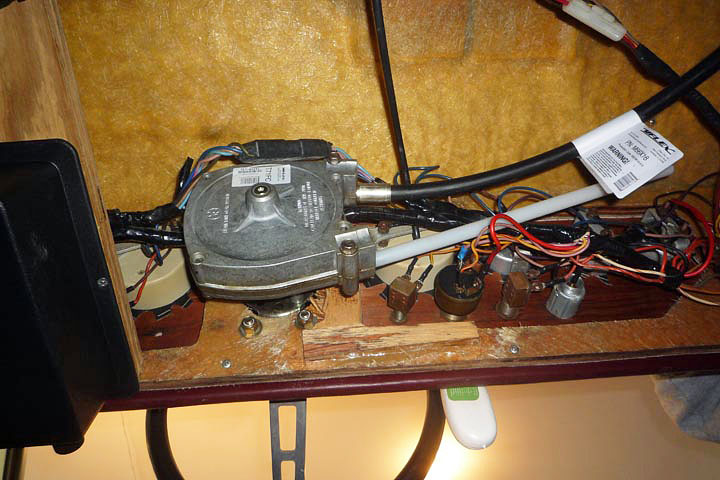
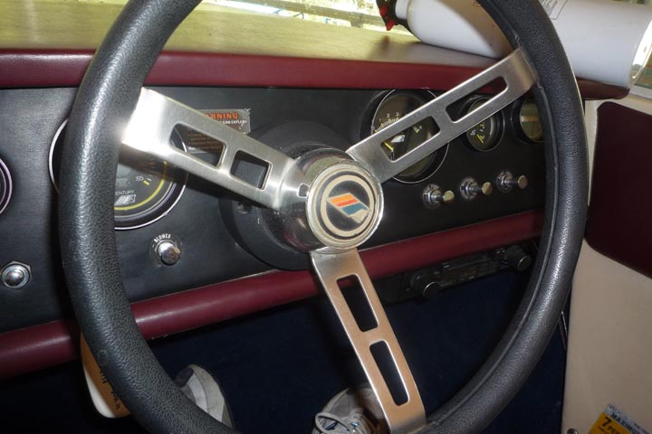
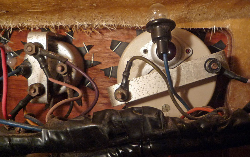
Here's a view behind the panel. Looking aft from floorboard. That's a "UFLEX" steering device. See this UFLEX website for more.
Control Panel and Instruments
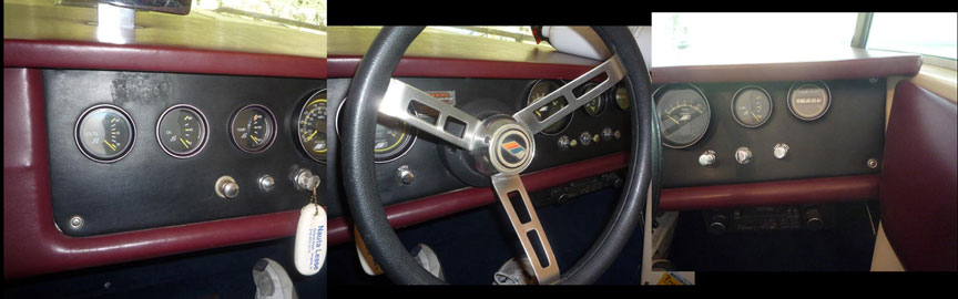
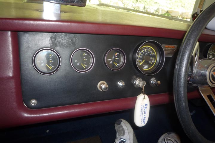
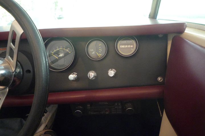
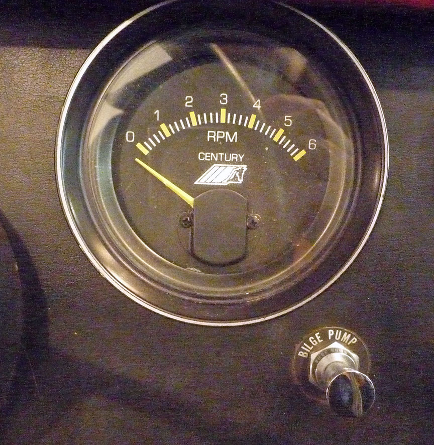
Here are some views of the panel's face.
Located below the instruments, left to right:
Cigar lighter
Horn
Ignition switch
Blower
Bilge pump
Navigation lights
Panel lights
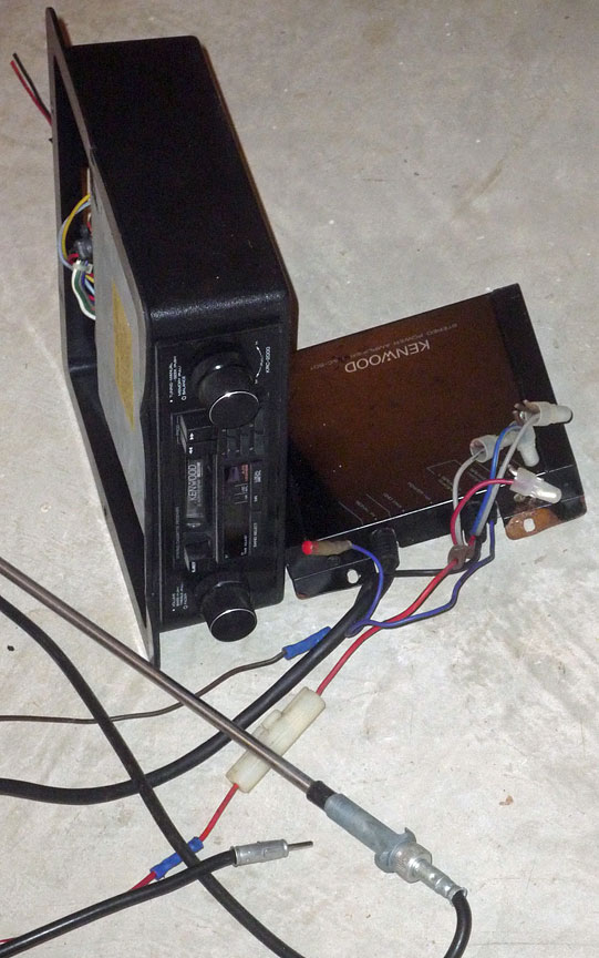
(The radio has been removed since this photo was made.)
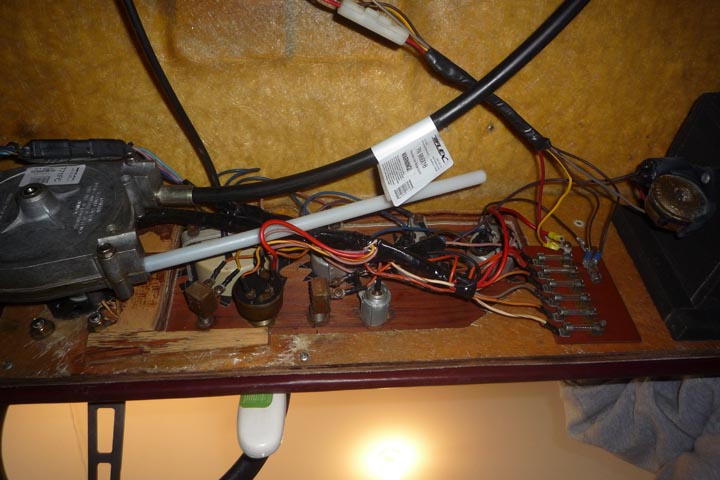
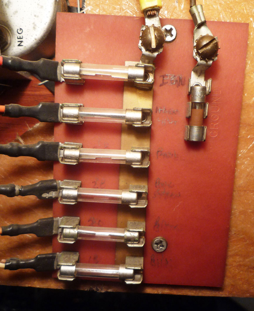
Fuses
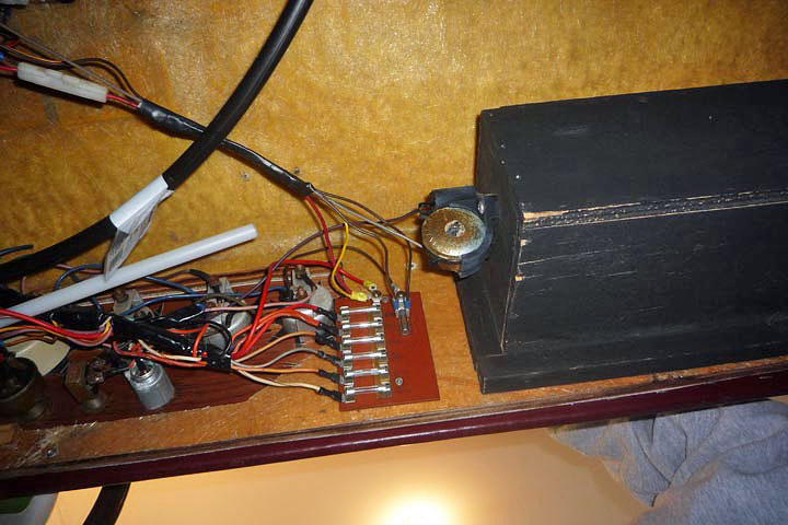
The fuse panel can be seen in the photo(s) at the top of the page. Here are two close-ups of the panel. The first taken before removal of the radio and amplifier (with their "in-line" fuses), the second after removal.
The fuses protect the (confirmed) circuits as listed below (numbered top to bottom.)
Ignition -- 20 amps.
Horn and Cigar -- 10 amps.
Panel lights?? -- ?? amps.
Nav. Lights -- 20 amps.
Blower -- ?? amps.
Bilge Pump -- 10 amps.
I do not understand why the ground buss holds the short fuse.
The lower close-up photo (above) was taken after the tuner and aux. amplifier were removed 12/17/11. A "before" photo of wiring is at upper right, this page. CLICK HERE to see the components removed.
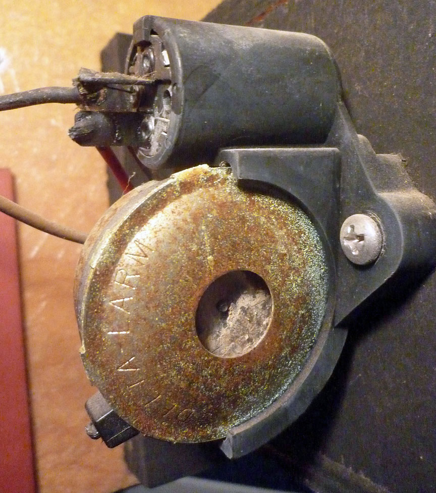
Alarm
I'm not sure what this alarm's function is. See its location (on side of glove box) in top photos. On one boat I've operated, a fume sensor was supposed to set off an alarm if fumes were detected, but it did not function -- giving a false sense of security. Fred Costa provided this info on facebook: "Low oil pressure, thats why key on without engine running sets it off. High temp should also set it off if wired correctly."
But now I know -- this alarm sounds if the ignition switch has been left "on" without the engine running for a short period of time -- maybe 30 seconds or a minute. I have not timed it.
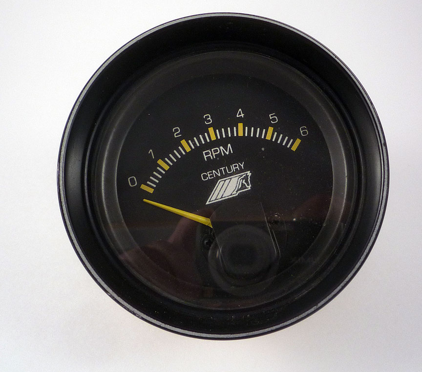
Tachometer
The tach did not work when I bought the boat. The technicians at the boat yard said there "was a signal" at the back of the tach, but it was not "reading" the signals. At the 2011 Lake Geneva ACBS show, I met Dale Kocian, who restores instruments. I may send the tach to him at Kocian Instruments for repair.
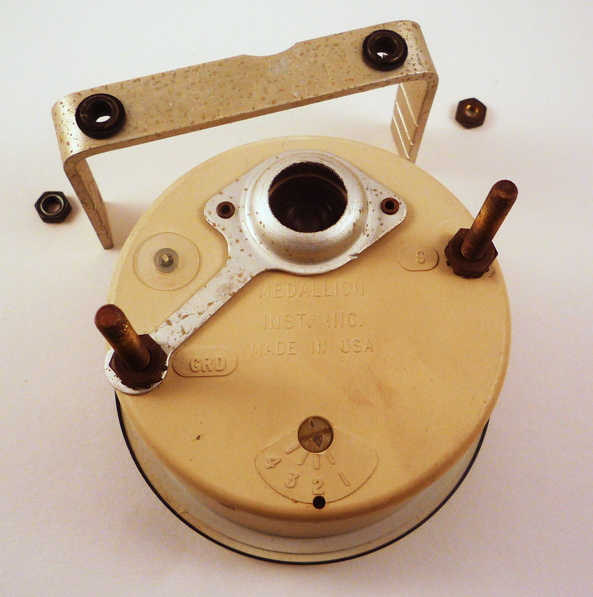
Mark says the tach is probably operated by the "pulse" from the negative side of the coil, and that I should be able to determine if there is a pulse using a simple 12 volt test light from the negative post of the coil to ground, then cranking the engine using the starter (key) switch. Mark also suggested "working" that switch on the back of the tack (to "clean up" possible corrosion, etc.)
But now I wonder if the following instructions apply to my boat, which has an "after market" ignition system:
INSTRUCTIONS
I have checked out both the "power" and the "pulse" circuits to the tach. I recorded the tests and have displayed the videos on youtube. They are easy to find -- just search for the user name "gmaclaren" -- no "quotes." (Or
Tachometers, in their most basic forms, are devices that measure the speed of an object. Most commonly, they measure the rotation of a mechanism, like the engine shaft in a car. Traditionally, tachometers are dials with a needle pointing to the current speed in RPMs (revolutions per minute). However, with the onset of new reading systems, the use of digital tachometers has risen sharply.
Dial
The dial tells the driver the tachometer's reading. In a car, it is located on the dashboard. The instrument itself measures the RPMs of the engine drive shaft. The device is necessary in order to regulate how hard the engine is being worked. The way in which the measurements themselves are taken, though, can vary.
Generator
Engines with ignition systems can use a small generator attached to the engine drive shaft. In this case, the tachometer is actually a voltage meter, meaning that it counts the pulsations of voltage in the ignition system. The output voltage is proportional to the shaft's speed so measuring voltage is converted into an accurate measurement in RPMs.
The voltage is generated via a permanent magnet on the shaft. There is a toothed wheel made of iron, which becomes magnetized as the magnet passes the teeth. Then, as the magnet rotates away from the teeth, the wheel becomes de-magnetized. As these changes occur, an electric field forms around the permanent magnet. This field affects the electric charges in a wire coil that surrounds the magnet, generating electricity. As the tooth approaches the magnet, the current flows one way in the coil. As the tooth moves away from the magnet, the coil's current switches direction. The tachometer reads the frequency with which the coil's current changes direction.
Additionally, if the engine turns more quickly, the change in the magnetic field becomes more radical, generating higher voltage. The tachometer also uses this information to inform its reading.
Sparks
A simpler method is to measure the rate at which sparks are released into the engine's cylinders. This is obviously only useful in a gasoline engine, which uses spark plugs to provide the explosive heat energy that moves the vehicle.

