|
Schematics, etc.
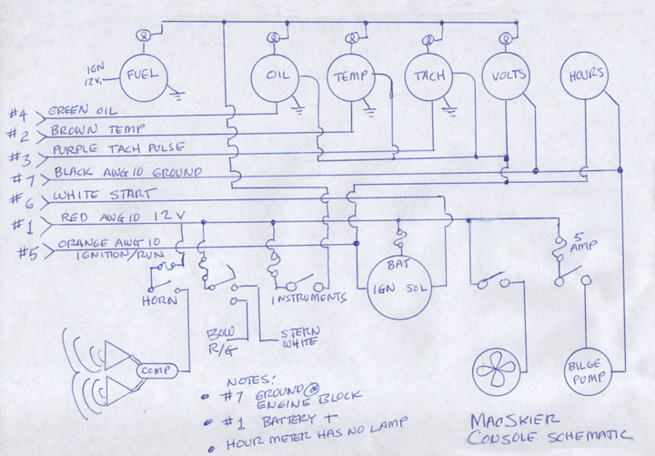
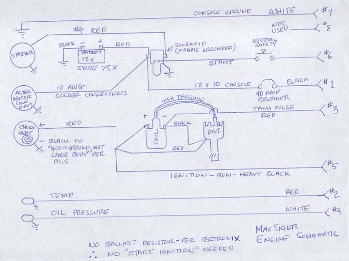
Here are a few of the drawings made while rebuilding MacSkier. A number of anomalies made it important to make some schematics. Click on any image for a larger version.
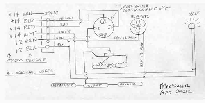
- When built in 1972 the boat had a mechanical fuel gauge which was viewed via a round window in the aft deck. It was replaced an electric gauge by a DPO. But the DPO did not run a wire for the light in the gauge. (The light may have been operated along with the "360" white light, but if so, I did not notice before the rebuild.)
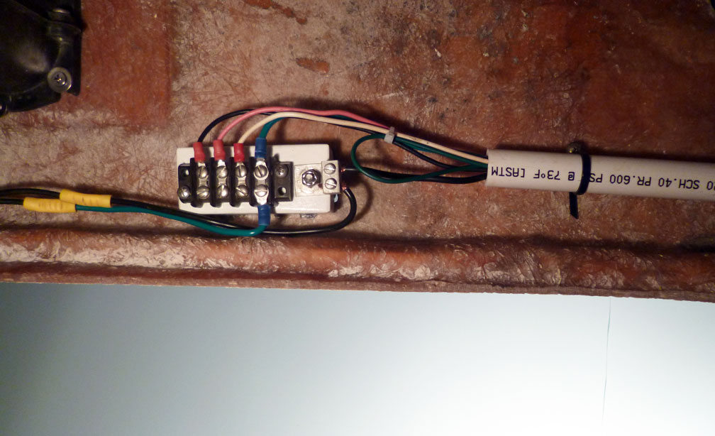
- The bilge blower was wired with 14 AWG wire, as was the aft deck common, or "ground." The blower draws about 4 amps, so IMO would be better served with #12 wire. Some of the aft deck wiring.
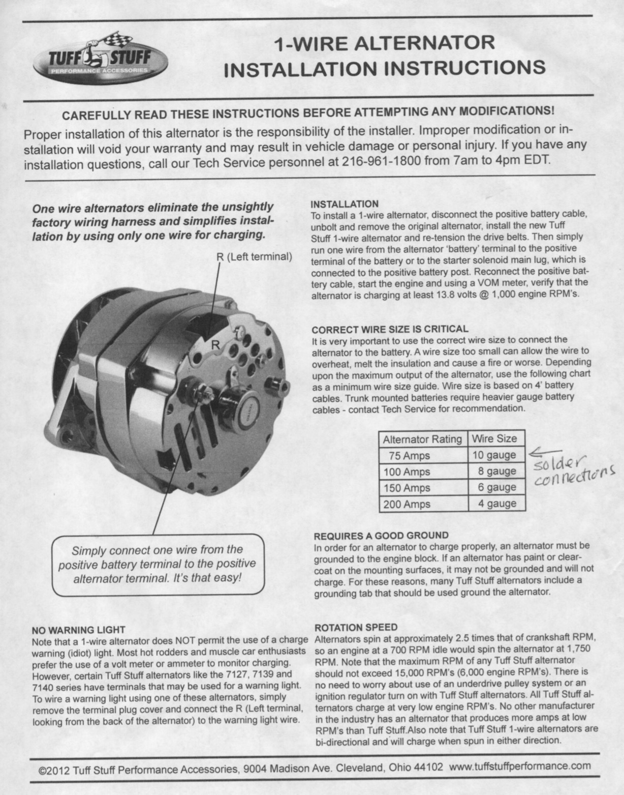
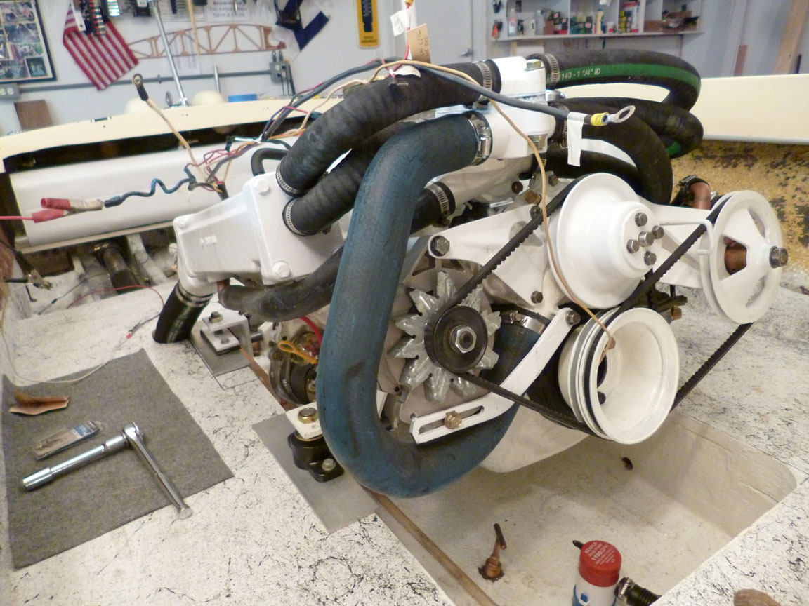
- A new marine "one wire" alternator (not the one described here) was installed (along with the new engine) in the boat. This eliminated the need for at least one wire and a separate regulator.
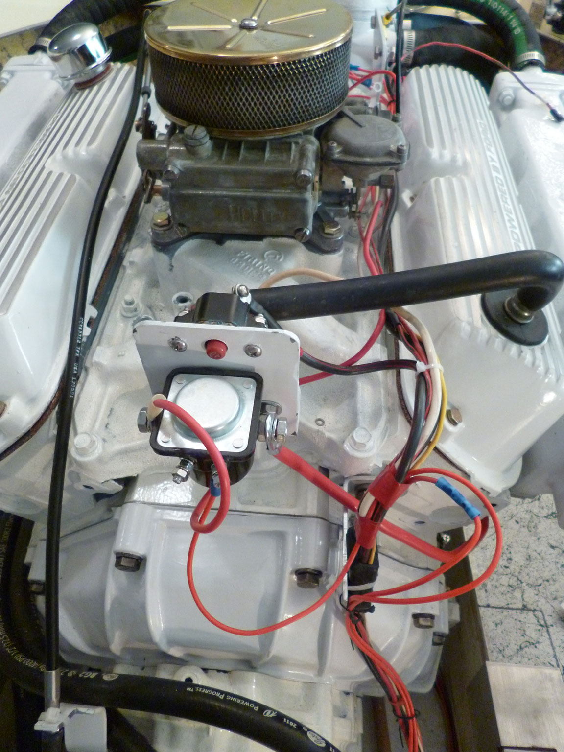
- The fuel filter/water separator was moved aft, making a much "cleaner" engine compartment (installation completed 11/30/15).
- Electronic ignition was installed. The manufacturer's instructions tells us to eliminate the ballast resistor, so that eliminated the need for "bypass while starting" wire.
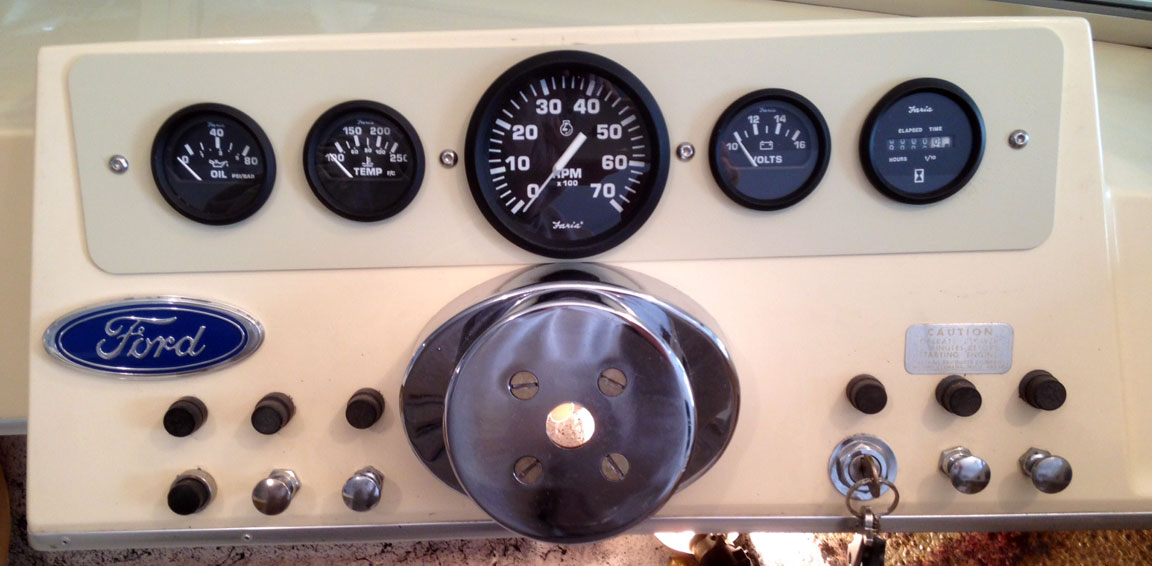
- An "accessory power outlet" (cigarette lighter receptacle) was removed from the control panel and a new one installed "out of sight" behind the panel. (I've found it handy to use my car's GPS in the boat.) For now, a Ford emblem covers the hole. In future, a new panel (of SS) will cover both 1) this area, and 2) the area now containing fuse holders, switches, etc. The panel as of 11/25/15.
- An ugly-looking, square-faced depth finder was removed from the panel, and an hour-meter installed. (The hour-meter does not contain a lamp. If I had known this when I received it, I woud have sent it back.)
- The four "push-pull" switches have been replaced with new ones.
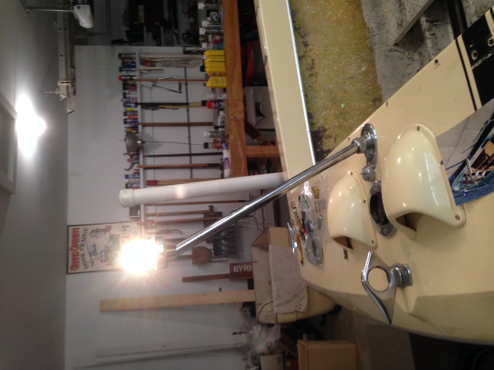
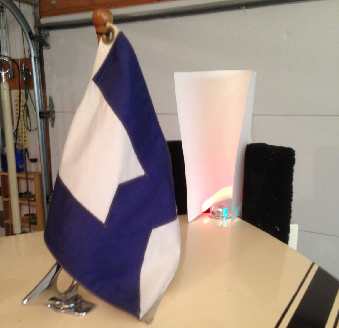
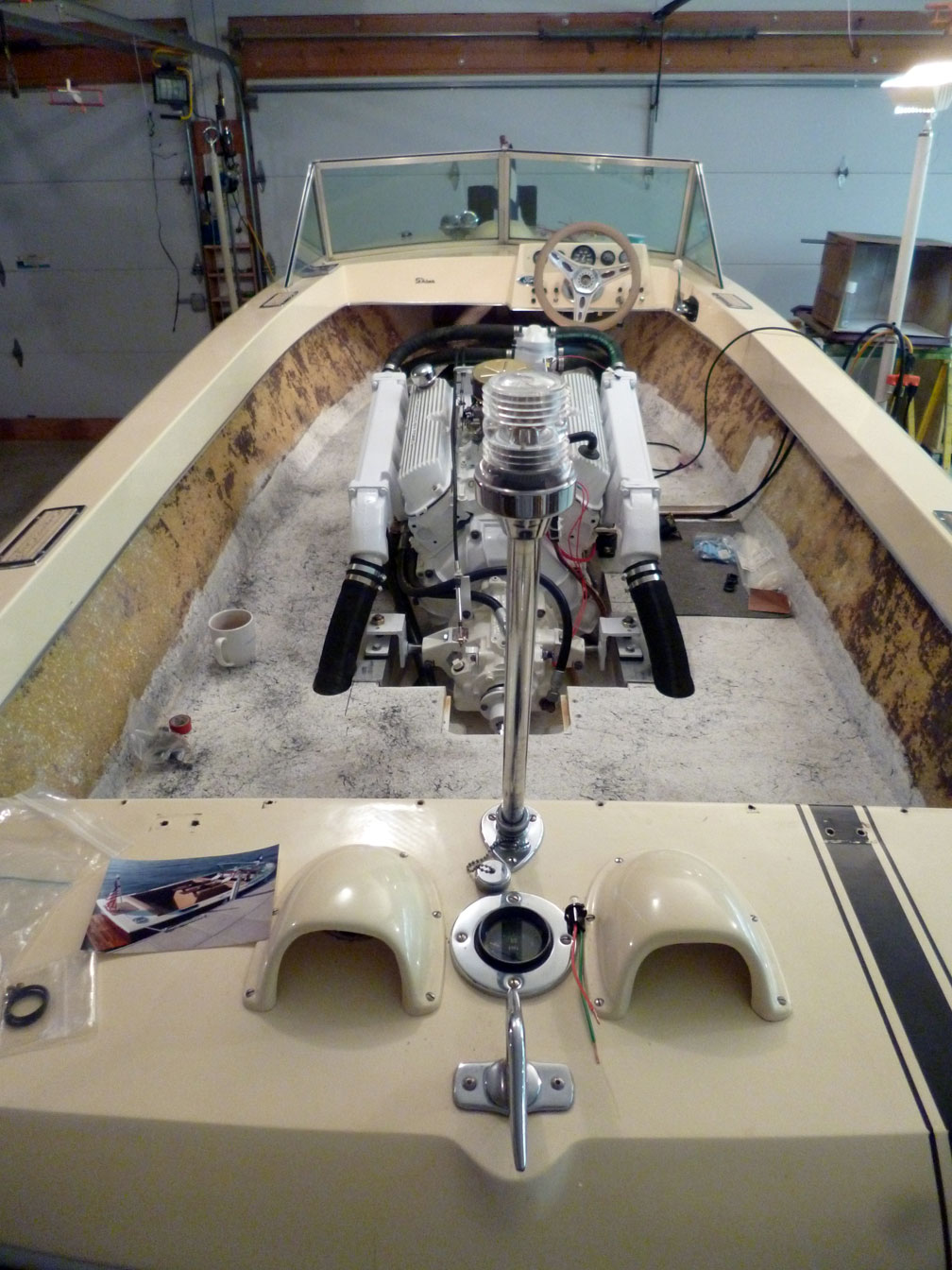
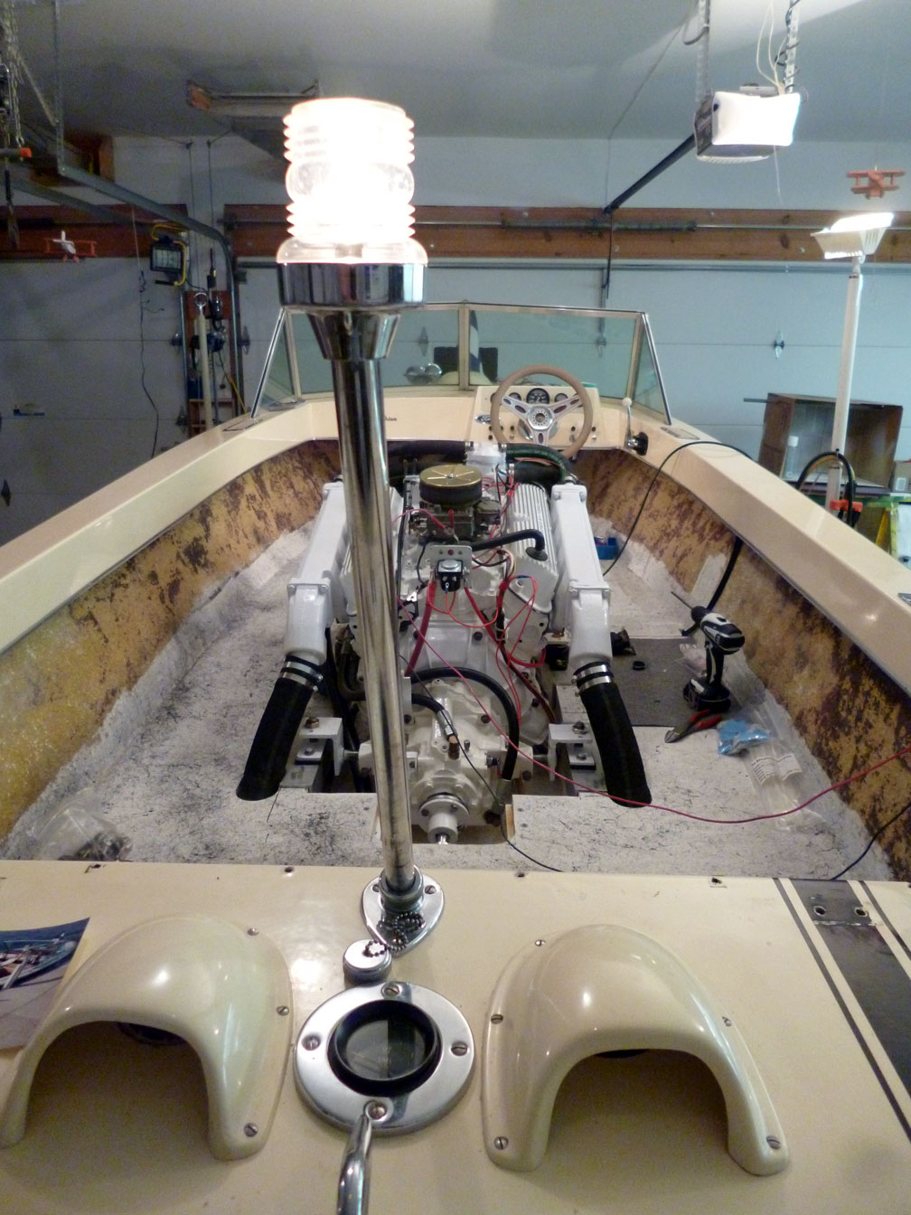
- The "360" white light has been repaired.
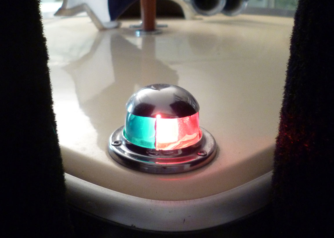
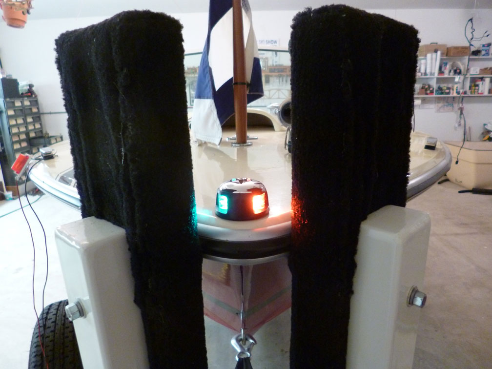
- The old bow nav light (another photo here) has been replaced with new LED unit.
- We're running out of excuses to fire up the engine.
- 12/5/15 -- The wires have been run and new mounting brackets designed and fabricated. It looks like this today. Still have to "wrap" the wires to make a neat-looking harness.
- 12/9/15 -- Ooops, misplaced that roll of harness tape. Two more rolls on order -- should be here Friday, the 11th. PHOTO PHOTO PHOTO So, still have to "wrap" the wires to make a neat-looking harness. (READY FOR WRAPPING)
A good friend (and double-E) answered my question about a pules for the tach:
"The tach needs a signal that pulses. It can get it from the coil or from the alternator.
"For the coil, the tach usually gets the signal somewhere along the wire between the coil and the points because the opening and closing of the points creates the pulse. The pulse is not nearly as strong on the wire from the coil to the ignition (usually the + side of the coil if the battery is negative ground.) which is usually the wire that has the ballast resistor. Because newer engines don't have points but have an electronic module, the signal is usually taken off where the wire from the module (or points) connects to the coil. With a negative grounded battery, this is the side of the coil marked with a - symbol. However, sometimes replacement coils are not installed properly, so it is worth while tracing the wires to be sure the coil - terminal is in fact the one that goes to the points or the ignition module.
"If you use the alternator connection, most alternators (but not all) have a terminal on the back for the take-off. This terminal connects to one of the windings inside the alternator before the rectifier diodes convert the ac to dc. This is usually used for the signal on diesel engines but can also be used on gasoline engines. Because the alternator is usually driven by a pulley with some unknown ratio to crankshaft rpm, tachs designed for connecting to alternators usually have some switches and sometimes an adjusting screw on the back to calibrate the tach so what it reads is actually the rpm of the engine."
HOME
Another pretty good web page by
Grant MacLaren

|